More about windows. This includes thermal bridges and comparison between installation costs and running costs of windows.
Showing posts with label 熱橋. Show all posts
Showing posts with label 熱橋. Show all posts
Friday, 18 December 2020
Monday, 2 November 2020
How to slow Down Heat Part 2: Confounded by Compound Insulation
The sums don't quite add up for the problem we looked at earlier. The two calculations for compound insulation give a slightly different answer.
You can see the calculations with my terrible handwriting here. Or just go straight to the video below, which is much lighter on maths.
This is the calculation looking at parts of the wall in parallel first.And this is how to calculate looking at the parts of the wall in series first.
We don't get the same answer. Here's why and what we can do about it.

Thursday, 29 October 2020
How to Slow Down Heat
Now that we know it's impossible to stop heat, let's see if we can slow it down!
Wednesday, 11 November 2015
Lesson 4. How to slow down heat
Some questions for starters:

 The parallel method is to break it up into different bits of wall, work out their U values, then average those.
Then I got to the last question from the beginning of the lesson. In preparation for the lesson I'd been looking for a climate where you don't need any insulation. This would have to be between 20 and 30 degrees pretty much every day. The climate in the Caribbean is fairly constant and not too hot, but the best I found was in Ecuador and Columbia.
How do you stop heat flow?
What is a "thermal envelope"?
What is "heat loss form factor"?
What can nature tell us about building a low-energy house?
Are there are situations when you don't want high insulation and low form-factor?
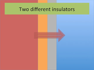
The first four were revising what happened the previous week. This was especially helpful for two of the students who had missed the last lesson. After reminding them of fourier's law, I started making things a bit more complicated. What if there are two different insulators? You know, like in the real world. Because you can't just make a building out of glass wool. I guess you could try to make one out of polystyrene, but it would probably break. Or blow away.
First of all, and with the lobster fresh in our minds, I put a layer of glass wool on top of a layer of wood. I should have brought some actual insulation materials to the class to show the students what I was talking about, but I don't have any handy. I saw some bits of foam insulation on a building site yesterday, ready to go under the floor I think. If I go today, there may be some offcuts in their skip. I can probably work out better ways than prowling around builders' rubbish, but maybe not much better! And I wouldn't really want to bring glass wool to the class.
Anyway, absent of real materials, I used a powerpoint slide.
I told them about the R value, which is the inverse of the U value. This is resistance, and works just like resistance in an electrical circuit. This seemed to be familiar to most of them, not just the electrical engineer and the IT engineer in the class. In the same way as adding the resistors together, you can add up the resistances.
In terms of U value, it looks a bit more complicated: 1/U = 1/U1 + 1/U2 + ...
We have to remember it's upside down. This made one of the students laugh, as he remembered a scene in Pirates of the Caribbean. This equation is a bit like that. First you have to turn each of the maps (U values) upside down, then you have to turn the whole boat, I mean ship, upside down.
Next I showed them some insulation in parallel. We used the same amount of insulation, but instead of a 100mm layer of wood on top of a 100mm layer of insulation, we had 200 mm of wood next to 200 mm of insulation.
Before starting the calculation, I got them to guess whether this would be better or worse than the last case, and they guessed it would be worse, so the U value should be higher. Sure enough, when they did the calculation it came out worse.
Next, we delved further into the real world with a mixture of serial and parallel elements. 
There are two ways you can work this out. The serial method is to break it up into layers, calculate the R value for each layer, then add the R values. The middle element has 90% insulation and 10% wood, so you need to work out the U value of that by adding 9/10 of the insulation U value and 1/10 of the wood U value.
The parallel method is to break it up into different bits of wall, work out their U values, then average those.
I got half the class to work this out with the serial method, and the other half to work it out with the parallel method. I had hoped they would come up with their answers at more or less the same time, so I could then compare them. The two methods produce two different answers, and I was hoping for an argument to ensue, in which both sides would recheck their numbers, and insist they were correct.
In practice what happened was that the highly numerate students finished working out the first calculation, I suggested they try using the other method, which they also worked out, realised the two answers were different, and the less numerate students were still struggling with the first calculation. By this stage of the course, I should really have worked out which students were which, and paired the mathematical with the non-mathematical, so they would help each other, then go and help other pairs when both of them had finished. I did regroup them to some extent at the beginning of the lesson, but need to work a bit harder next time.
So we established that the two methods produced different results. Here was another of those important lesson that has relevance way beyond low energy building. If you do two calculations and get two different answers, there are three possible reasons: one of the answers is correct and you made a mistake in the other one; you made a mistake both times; or you are using two different methods that produce different answers. Getting calculations right is a good idea, since you could be paying for the wrong answer in heating or cooling bills for the rest of your life. A few minutes checking the calculations is worth it!
So, the two methods gave different answers, and I wondered, in a rhetorical sort way, whether the formula for serial or the formula for parallel insulation was incorrect. One student suggested the parallel calculation was wrong because this wouldn't happen in the real world. Why on earth would anyone put insulation between bits of wooden structure?
I had to tell him that alas, this was often the way insulation was used. Building structures are frequently made up of pillars, and builders see insulation as a magical ingredient that can be added at random to reduce the heat loss. Although this was the wrong answer, I was quite pleased that this student had learnt more about insulation in a couple of lessons than some architects seem to have in their whole careers.
The parallel calculation is incorrect, not because it doesn't happen, but because there will be some lateral heat flow between the two kinds of insulation, so the heat is moving in two dimensions. For the serial insulation, heat is basically flowing in one direction, so fourier's law holds true.
To work out what is really going on within complex structures, you need to use finite element analysis, and software like Therm. The computer makes a grid of squares and triangles, it calculates heat flow between each element, and repeats the process for every element several times until the numbers stop changing. Then it can tell you what the temperature and heat flux will be throughout the wall. You can see more details in my previous blog post slits in the envelope.
Everywhere else either gets hot or cold, or both.
40% of power in Mumbai is used for air conditioning, and it has been estimated that by 2060 the energy used worldwide for cooling will exceed the energy used for heating. The US, original home of the air conditioner, and country of vast wealth uses more electricity for cooling than Africa uses for everything. If I had invented an air conditioner and was wondering which continent needed it, I would have made a different choice!
40% of power in Mumbai is used for air conditioning, and it has been estimated that by 2060 the energy used worldwide for cooling will exceed the energy used for heating. The US, original home of the air conditioner, and country of vast wealth uses more electricity for cooling than Africa uses for everything. If I had invented an air conditioner and was wondering which continent needed it, I would have made a different choice!
Air conditioning may seem like a great idea for individuals with a bit more cash in their pocket who want a bit more cool in their lives, but it's a bit of a disaster for global warming. As well as the energy used by the air conditioners, often from coal-fired power stations, the refrigerants used in the air conditioners are often 4,000 times worse than CO2 as a greenhouse gas.
And of course more energy use and more refrigerants leaking into the air will lead to hotter temperatures and more need for air conditioners.
People often think that insulation will make buildings hotter in the summer, but insulation does not make anything hotter. It just slows down heat flow. So if it's cooler inside and hotter outside, then less of the heat will get in. Of course there are differences. Many things in a house create heat, such as electrical appliances, hot water and people. If you are in a heating situation, these are all on your side and will reduce the amount of heating you need. In a cooling situation these are all enemies for which you need extra cooling.
Also, colder places are a lot colder than hotter places are hot. The average winter temperature in Yakutsk, probably the coldest city in the world, is -34°C. The average summer temperature in Kuwait is 38°C. There seems to be some symmetry to these numbers, but remember the temperature we want to live in is around 25°C, so Yakutsk is four or five times further away. Also cold weather seems to be more deadly than hot weather.
We tend to think of Australia as a hot country, but cold weather kills more people in Australia than hot weather does. However, we should also note that more people die of cold in Australia than in Sweden. Almost twice as many. Sweden is not a hot country, but Swedish houses are insulated. If Australia insulated its houses less people would die. People who aren't paying with their lives would pay less on their heating bills. If Mumbai used more insulation they would use less energy for their cooling.
I didn't have time but was hoping to talk a bit about thermal mass, and whether that can be used instead of insulation. The short answer is that it can't.
So far we've got to the following implications for the basic design decisions: keep form factor low, put insulation on the outside, and beware of thermal bridges.
References and further reading:
World set to use more energy for cooling than heating
Guardian, 26th October, 2015
Artificial cooling makes hot places bearable—but at a worryingly high cost
Economist, 5th Jan, 2013
Australian houses are just glorified tents in winter
The Age, 11th June 2015
Guardian, 26th October, 2015
Artificial cooling makes hot places bearable—but at a worryingly high cost
Economist, 5th Jan, 2013
Australian houses are just glorified tents in winter
The Age, 11th June 2015
Tuesday, 24 January 2012
Japanese airtightness measurements suck
Apparently in Germany, when they do an airtightness test on a house, they test both over pressure and under pressure. In other words, they shut all the windows and doors, and put a blower on one of them to blow air into the building until the pressure gets to be higher than outside, then they measure how quickly the air starts leaking back in again. Next they blow air out so the pressure is lower inside, then they measure how quickly the air starts leaking in again. They take the average of the two values to get the airtightness of the house, which is measured, at least for Passive House certification, in the number of times the air will change per hour. The passive house standard is 0.6.
In Japan, they usually only have the equipment to do the under pressure measurement, which apparently is usually a little better. So, in a sense, Japanese airtightness measurements suck.
They did another airtightness test in December, which I'm still waiting for the results for. I should have done this months ago, but I've just now started looking carefully at the results from August. The experts said that we needed a C value of 0.2, but we only got 0.3 which was not good enough. They said that this was a reverse calculation, making it sound really difficult.
Never trust experts, especially if they make things sound really difficult and complicated. If they do that, it's a sign that they don't know what they're talking about. If they do know what they're talking about it, they should be able to explain it and make it simple.
Anyway, as a result of this 0.3 that should have been 0.2, we became very sceptical of the Compriband's effectiveness, and added caulking around each window to improve airtightness. We had previously planned to add a layer of insulation around the inside of the window frame, on the few centimetres of wall perpendicular to the window. This insulation would have reduced the thermal bridge effect of the window from something like 0.04 W/mK to 0.03 W/mK. This doesn't look like a lot, but when you think of all the windows in the house, and measure around each frame, there are something like 80 metres, and there are 70,000 degree hours temperature difference over the part of the year that needs heating, so it amounts to about 50 kWh per year.
Anyway, it was basically presented to me as a choice between putting caulking around the window frames, to improve the airtightness, which wasn't good enough, or carrying on with the plan to insulate around the frames and improve the thermal bridges. The caulking was going to work out more expensive than the insulation, but the builders offered to cover the extra cost, so it would make no difference to my pocket.
The decision had to be made quickly as other parts of the wall were about to go up, and the frames would no longer be accessible. I agreed to them adding the caulking, which the airtightness and insulation people went ahead and did.
But, while waiting for the results of the latest airtightness test, I started looking a little more closely at the figures of the last one. I should have done this ages ago, and in fact I've been waiting for an opportunity to talk with them and find out more details of this devilishly difficult conversion between the C value and the number of air changes per hour.
According to the figures the airtightness experts emailed me 4th October, almost two months after the test, the result was 259 cubic metres per hour at 50 Pa pressure difference. The bit of the form where the number of changes per hour should have been was blank, I guessed because they didn't have the figure for the volume of the house. According to the Passive House database, the volume was 500 cubic metres. Obviously this is not the exact volume, but it's close and serves as a design volume. Taking this, and the 259 cubic metres per hour, that looked to me like 0.52 times per hour, which meets the PH standard.
So, I surmised that either 1) my calculations are incorrect and it's much less straightforward than [volume per hour / total volume]; 2) the design volume of the house (500 cubic metres) is a lot more than the actual volume; or 3) the architect or airtightness experts were too lazy or too incompetent to perform a straightforward calculation. My money was on 3.
I spoke to the architect on the phone, broken into two or three calls as he kept having to find information, or calls back because he had found more information. The figure he had was 0.542 exchanges per hour at 50 Pa. The actual volume of the house is 478.1 cubic metres. I'm beginning to wonder whether the airtightness people sent him a different copy of the results to the one they sent me... Why would they do that?
After first denying that the caulking had anything to do with the insulation and suggesting that the airtightness people had done it as an act of charity, he later came back and conceded that yes, the first airtightness test had met the standards, although they had told us that it had not, and that no there had been no need to add caulking on top of the Compriband, and yes, we could have had the extra insulation around the inside of the window frames and reduced the thermal bridge effects.
Another factor prejudicing them against extra insulation was that in some places the insulation would have stopped the windows from opening. As far as I was concerned though, it was a fairly straightforward choice.
Not sure exactly whether he's going to do anything about it, but he did at least say sorry, and not really related but he would get us a ventilation system with a bypass, and would cover the cost for it.
Maybe a complete coincidence but the airtightness and insulation people did the caulking work, and also did the airtightness tests.
There's something very satisfying about letting people know that they have done you wrong, but perhaps only relative to the much deeper dissatisfaction of feeling that you have been done wrong to.
In Japan, they usually only have the equipment to do the under pressure measurement, which apparently is usually a little better. So, in a sense, Japanese airtightness measurements suck.
They did another airtightness test in December, which I'm still waiting for the results for. I should have done this months ago, but I've just now started looking carefully at the results from August. The experts said that we needed a C value of 0.2, but we only got 0.3 which was not good enough. They said that this was a reverse calculation, making it sound really difficult.
Never trust experts, especially if they make things sound really difficult and complicated. If they do that, it's a sign that they don't know what they're talking about. If they do know what they're talking about it, they should be able to explain it and make it simple.
Anyway, as a result of this 0.3 that should have been 0.2, we became very sceptical of the Compriband's effectiveness, and added caulking around each window to improve airtightness. We had previously planned to add a layer of insulation around the inside of the window frame, on the few centimetres of wall perpendicular to the window. This insulation would have reduced the thermal bridge effect of the window from something like 0.04 W/mK to 0.03 W/mK. This doesn't look like a lot, but when you think of all the windows in the house, and measure around each frame, there are something like 80 metres, and there are 70,000 degree hours temperature difference over the part of the year that needs heating, so it amounts to about 50 kWh per year.
Anyway, it was basically presented to me as a choice between putting caulking around the window frames, to improve the airtightness, which wasn't good enough, or carrying on with the plan to insulate around the frames and improve the thermal bridges. The caulking was going to work out more expensive than the insulation, but the builders offered to cover the extra cost, so it would make no difference to my pocket.
The decision had to be made quickly as other parts of the wall were about to go up, and the frames would no longer be accessible. I agreed to them adding the caulking, which the airtightness and insulation people went ahead and did.
But, while waiting for the results of the latest airtightness test, I started looking a little more closely at the figures of the last one. I should have done this ages ago, and in fact I've been waiting for an opportunity to talk with them and find out more details of this devilishly difficult conversion between the C value and the number of air changes per hour.
According to the figures the airtightness experts emailed me 4th October, almost two months after the test, the result was 259 cubic metres per hour at 50 Pa pressure difference. The bit of the form where the number of changes per hour should have been was blank, I guessed because they didn't have the figure for the volume of the house. According to the Passive House database, the volume was 500 cubic metres. Obviously this is not the exact volume, but it's close and serves as a design volume. Taking this, and the 259 cubic metres per hour, that looked to me like 0.52 times per hour, which meets the PH standard.
So, I surmised that either 1) my calculations are incorrect and it's much less straightforward than [volume per hour / total volume]; 2) the design volume of the house (500 cubic metres) is a lot more than the actual volume; or 3) the architect or airtightness experts were too lazy or too incompetent to perform a straightforward calculation. My money was on 3.
I spoke to the architect on the phone, broken into two or three calls as he kept having to find information, or calls back because he had found more information. The figure he had was 0.542 exchanges per hour at 50 Pa. The actual volume of the house is 478.1 cubic metres. I'm beginning to wonder whether the airtightness people sent him a different copy of the results to the one they sent me... Why would they do that?
After first denying that the caulking had anything to do with the insulation and suggesting that the airtightness people had done it as an act of charity, he later came back and conceded that yes, the first airtightness test had met the standards, although they had told us that it had not, and that no there had been no need to add caulking on top of the Compriband, and yes, we could have had the extra insulation around the inside of the window frames and reduced the thermal bridge effects.
Another factor prejudicing them against extra insulation was that in some places the insulation would have stopped the windows from opening. As far as I was concerned though, it was a fairly straightforward choice.
Not sure exactly whether he's going to do anything about it, but he did at least say sorry, and not really related but he would get us a ventilation system with a bypass, and would cover the cost for it.
Maybe a complete coincidence but the airtightness and insulation people did the caulking work, and also did the airtightness tests.
There's something very satisfying about letting people know that they have done you wrong, but perhaps only relative to the much deeper dissatisfaction of feeling that you have been done wrong to.
Monday, 14 November 2011
Not too late for the punctual thermal bridge - The North side revisited
One good thing about having a 12 month delay in a building project is that it gives you plenty of opportunities to reconsider previous decisions. You spend hours, days and weeks thinking about things, then come back to them months later with a fresh opinion. Then you try to remember why and how you came to the decision in the first place.

There are always many ways of doing things, and often there is something radical that you've never seen in a house before. There is usually a good reason why it has never been seen, either that there is a flaw in the idea, or the conservative nature of builders and architects. Materials and science have moved a great deal in the past few decades, but building sensibility still goes back hundreds of years. A lot of dimensions can be calculated, rather than guessed by eye or by rules of thumb, and this could reveal extra possibilities, or if the architect doing the calculations is semi-numerate, it could further restrict the possibilities.
Let me digress into a couple of examples from aeronautics. In the 1940s when Howard Hughes made his eight-engined Spruce Goose, the largest flying boat ever, about the same length as a 747, but with twice the wing area, the science of aerodynamics was young and aircraft design was more of a craft. The wings, scaled up from smaller working designs, were so big you could walk down the inside. A little bit earlier, in the 1920s when airships seemed the only logical alternative to crossing the atlantic by sea, and R100 airship was being designed, they needed to calculate the stresses on each beam and wire of the massive frame that kept the balloon full of hydrogen. They used a computer for this, which at the time was a person with a slide rule and a pad of paper. If they found that any of the wires had negative tension, they would send it all back the designer.
Back to our little world, at the end of the day, you just have to make a decision, and then stick with that decision, and convince yourself it is the correct one. Then move on, as there are plenty more decisions to make.


Of course, when the house is built and you start living in it, and those decisions become solid objects, you find out whether you did the right thing or not, and if you want to find out whether it was the right decision, then keep reading. When we do move in, though, after the investment of time and money, there's a high chance that I'm going to consider the house to be close to perfect, and I'll look around, through or away from any problems that there are, and do my best to enjoy the good bits. Human beings are, after all, very flexible animals when it comes to living environments.
It has been very tempting, whenever part of the building comes up that we have not been entirely sure about, to take the full opportunity offered by the questions "are you sure?" or "do you really want to do this?" or "what, exactly, are we supposed to do here?" that the builder asks the architect, luckily in our presence.
I suspect that, had we not started to get heavily involved with the builder, insisting that we are involved in any meetings with architect, and if I hadn't been visiting the building site, with a camera, pretty much every day, things would have been very different. For a start, we probably would have moved in a few months ago. All the questions that we see being asked, as the builders scratch their heads over the architect's drawings, would have been worked out in some haphazard fashion, filled with builders guessing what the architect meant and hoping for the best, and the architect demanding constructions based on his own prejudices, either forbidding materials that he doesn't like, or using them indiscriminately because we had the nerve to ask him to use them. A lot of the time, I suspect the architect would have just presented it as a concept in pencil on paper, and left it to them to work out how to make it. Almost none of the time would he have been thinking about what we really want.
So, anyway, when it came to the roof over the front door, we were able to change the plan.
The plan had been to have a sloping, transparent roof over the two doors on the north side of the house. The front door is to the west of the north wall, then there are seven steps up to the entrance to the este room. With the doors being at different heights and there being windows and glass doors, it seemed like a good idea to have a transparent roof, at an angle.
It seemed to me a very bad idea to puncture the thermal envelope, but according to the architect, this was just too difficult to do without puncturing the wall with beams, although in a couple of days the carpenter seems to have managed to remove the protruding beams, and construct a new roof. Evidently moving hammers, saws and three-metre lengths of wood is more difficult than moving pencils, erasers and the computer mouse.
It had always seemed to me a good idea to have a transparent roof, as this will let in more light, but when it came to it, the architect had no idea how this was going to be done, and the ideas he had all sounded like they would look terrible. One big issue with the roof is that it is likely, at some point, to be subjected to falling bits of ice from the roof above. These could actually be quite large and serious as the roof is highly insulated, so the heat escaping from the house is not going to have a very good melting effect. Also there is a bit of wall sticking up from the north roof to the higher south roof, so the top part of the roof will be in permanent shade for half the year. And the north roof has quite a shallow slope, so snow is likely to stay there for a while, going through a melting-freezing cycle and getting harder and harder. Anything transparent is not going to be as strong as a solid roof, and liable to be damaged by such falling ice. Then there are fire regulations, which need a whole new post to cover both their simplicity and the extent to which they are interpreted and ignored.
Thursday, 7 July 2011
The Levi Strauss effect
One way of explaining the thermal bridge effect is retelling a story from the history of fashion. This story comes many years after Levi Strauss started using a fabric of Nimes (in France) for trousers in the style of Genoa. To increase the strength of these denim jeans, he put copper rivets in strategic places. In the early garments, one of these rivets came where four bits of cloth meet at the crotch. At least until one day in 1933 when Levi Strauss president, Walter Haas Sr. was out camping, wearing a pair of 501s, and he sat down by a campfire. He hadn't looked very carefully, and on the seat was an iron that had just been in the fire.

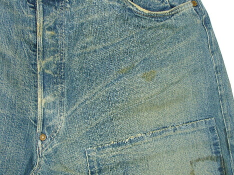
I'm sure you can imagine the effect of the hot iron on the rivet, the speed of the heat transfer, and the part of Mr Haas's body to which said heat was transferred. Needless to say, the crotch rivet was removed from the design.
This is a good example of a conflict between structural considerations and thermal considerations. In fact, the truth is a little less colourful, and although Levi Strauss used this story in an advertising campaign, the main reason for removing the crotch rivet was rationing of copper during the second world war, and economics played its hand.
Sunday, 3 July 2011
What's that sticking out of the envelope?
Just to follow on from the excitement of my last post on thermal bridges, here is a practical application.


Anyway, the result is six beams sticking out through the thermal envelope, some 120 x 180 mm, some 120 x 240.
Using Therm again, and starting with the pillar in the middle of the wall, we can estimate how much extra heat is being lost by this disturbance in the insulation-wall continuum. I looked at three cases. First, what would happen if the beam just reached the outside wall? Second, how about if it stuck out for 500mm? Next, what if it stuck out for a metre?
Using Therm again, and starting with the pillar in the middle of the wall, we can estimate how much extra heat is being lost by this disturbance in the insulation-wall continuum. I looked at three cases. First, what would happen if the beam just reached the outside wall? Second, how about if it stuck out for 500mm? Next, what if it stuck out for a metre?


There was virtually no difference between the 500mm protrusion and the one-metre protrusion (Ufactor 0.169874 versus 0.169972 W/m2K, around 15% extra heat loss for a unit area) so we probably don't need to worry about what exactly is happening to the beam after the first two or three hundred millimetres. Interestingly, the beam that just stopped at the outside wall did much worse (0.179 W/m2K, around 20% worse). I looked at 200 and 300 mm protrusions, and it looks like the ideal length for a protruding beam is somewhere between these two lengths. When I say the ideal length, obviously it's ideal not to have anything puncturing the thermal envelope.
The moral of this little tale so far, although of no use in our case, is that if you have insulation on the outside of the structure, and if you need to have wood sticking as far as the wall, it's better to have it stick out than flush with the wall, but much better to not have it stick out at all.
The colours in these pictures show thermal flux, white representing a high heat flow and black representing a low heat flow. So you can see that heat is leaking through the corners where the beam protrudes, but is leaking through the surface where it is flush. Practically, to the extent that we should be worried about this thermal bridge, there is a chance that on a hot and humid day in summer, these corners may have a much lower temperature than the ambient, and attract condensation. This is going to be outside in summer rather than inside in winter, and the outside is designed to stand up to rain. Also, it will be most critical when the temperature has just risen, and in these situations the humidity usually drops.
This kind of thermal bridge is called a punctual thermal bridge, where punctual refers to a puncture in space, rather than it's usual temporal meaning. It may in fact have the opposite meaning to that of "on time"--if you have a puncutal thermal bridge in your structure, it's probably too late!
For punctual thermal bridges, rather than considering heat loss per unit length, in W/mK, we need to consider the heat loss for each beam sticking out, in W/K. There are six of them, so once we have a number, we need to multiply by six.
While simple calculations only take into account one-dimensional heat flow (ie what the material is and how thick it is) Therm can simulate two-dimensional heat flows. In fact, and of course, the heat is in a three dimensional world, or in fact a four dimensional world as it's not a steady state, but temperatures are changing all the time. To use the two-dimensional models from Therm to estimate the three-dimensional situation of a beam sticking out of the wall, we can look at two slices of the wall, one vertical, which will include the pillar running up and down the whole wall, and the other horizontal, which will have a few centimetres of pillar in the middle, but the rest of the middle layer will be insulation.

As well as the situation above with a wooden beam sticking out from a perfect wall, as we'd see if we made a horizontal slice through the wall, we should consider this situation, where the middle layer of the wall is wood. For a unit metre of wall, with a metre of beam 240 mm wide sticking out, the U value for a section with the above situation is 0.170 W/m2K, compared with the ideal 0.145 W/m2K. If we look at a 240 mm square section beam, this will represent a difference of 0.006 Watts per Kelvin for the puncture. This amounts to 0.43 KWh lost per year, per beam. If we look at the more severe situation, as if the whole of the the middle layer were wood, the U value (again for 240 mm wide beam sticking one metre out) is 0.215 W/2K; corresponding to a difference of 0.017 W/K, again assuming a square section 240 x 240 mm. The real answer is likely between the two, around 0.011 W/K. Actually, the beams are smaller, so this is a mean estimate. A 120 x 240 mm beam looks closer to 0.006 W/K. There are six of them, so over the year, with 70,000 heating degrees, this comes to a significant 4.8 kWh per annum. We should still be within the passive house limit of 15 kWh/m2a (kilowatt hours per square metre of floor space per year).
It would have been better to work harder to keep this structure outside the envelope, although this may have had structural problems, stuck further out of the house and been more expensive. It could have been a lot worse. Wood is a relatively bad conductor (under 0.2 W/mK). Had it been concrete (around 1 W/mK) or steel (around 40 W/mK) it would have been much worse.
More info, and coincidentally the same example as in my last post here on wikipedia and more here here from the Passive House institute who have pioneered work on thermal bridges.
Tuesday, 21 June 2011
Slits in the envelope
In most places we have walls interrupted by occasional windows. The wall is a more-or-less uniform structure with three layers of insulation. Although the middle layer has a lot of wood in it, the first degree estimate (10% wood, 90% insulation) is near enough. We have data for the windows of the U values of glass and frame, and the thermal bridge "psi" value between glass and frame, and between frame and structure. U values come in W/m2K, in other words the heat flow per area per temperature difference. The psi value is in W/mK, so gives the heat flow along a line. A square window with one metre for each side will have an area of one square metre, but for the thermal bridge, the length is 4 metres. As window get smaller and less square, the relative effect of the thermal bridge gets bigger.


A rather wonderful piece of software called Therm can answer the question of how much heat is going to be lost from an actual wall structure, so we can see how close the actual U factor is of a wall with a wooden pillar running down it, compared to the prediction from the U values of 10% wood and 90% insulation.

You start by drawing the structure and setting each polygon to the appropriate material from the library of data the system has. In this picture, you can see the three layers of glass wool insulation in blue, a wooden pillar in the middle in orange, and a couple of layers of structural board in the other colour. Is that puce?
Next you set the boundary conditions. You can tell the software whether each surface is inside or outside, or whether to ignore it. You can consider a surface it adiabatic, in other words that heat is not going to flow through it at all. It would be very time consuming, and not particularly helpful, to model the whole house, and you usually want to find out about a particular bit of wall, or a boundary between roof and wall, or some kind of junction.
To model a wall, you can slice it in two places and put in an adiabatic surface in each, so you can get some meaningful estimation of what's going on. The main concern is heat flowing from inside the house out, so once you get far enough away from the part you're interested in, you can ignore any heat flowing along the walls.
In this case, the left side is outside, the right side is inside, and the top and bottom are adiabatic, so we're just looking at heat flowing from inside (where the temperature is assumed to be 20 degrees C) to outside (where it's assumed to be very cold - 18 degrees below zero). Of course the temperature will be changing all the time, as will the humiditiy, but this is just looking at a steady state in the worst case. Another piece of software called Wufi http://www.wufi.de/index_e.html will simulate the humidity conditions over a year or two, and show where moisture could build up in a wall or roof structure. That's not avaiable as a free download though!

To find out the thermal bridge effect of the wooden pillar running through an insulated wall, I compared three different structures. First, I made an ideal wall with a 50mm insulation on the inside, 120 mm in the middle, 12 mm of structural board, then 100 mm of insulation on the outside (1). Ideal, but of course it would not hold up very well! This has a U value of about 0.131 W/m2K.

Next I made a wall with the 120 mm middle layer completely made of wood (2). This has a U value of 0.187 W/m2K. In both cases 1 and 2, the U factor can be calculated directly from the U values of each component part. To do this you have to add up the R values (the reciprocals of the U values) which measure thermal resistance. There are also surface effect factors to account for convection, inside and outside, and factors to account for radiation. When you get to the surface, convection is the biggest cause of heat loss, but across the wall the heat is conducting.

Next, I made a wall with a 120x240 wooden beam in the middle. This is close to the real situation. As there is 240 mm of wood and 760mm of insulation, we would assume that the U factor of this bit of wall is 0.24 x U1 + 0.76 x U2, or 0.145 W/m2K. The Passive house spreadsheet also assumes this. In fact, the wall is conducting 0.147 W/m2K. This represents a difference of 0.002W/m2K. This corresponds to 0.002 W/mK along the length of the beam, and is the thermal bridge effect. This is small enough that we need not worry about it. Larger thermal bridge effects need to be added to the passive house spreadsheet. You can see the isotherms on this picture, showing how the temperature is distributed.

This picture, much more pretty, shows the temperature by colour, as you'd see from an infrared camera.
The next picture, perhaps even prettier still, shows the heat flux, with white representing the highest flux. So we can see which parts of the wall the heat is rushing through.

This software uses what's called a finite element grid, which I can remember hearing about in my lectures at university. I think I nodded off shortly after them, only to wake up just before my finals, but along with the thermodynamics, I realise now that at least something stuck from those days, and at least in some tiny way I can call myself an engineer. I'm not sure whether it was the result of my university study, or whether it was instilled in me from earlier by my father. Perhaps the essence of engineer goes further back, and courses through my veins from generations living in the harsh and unyielding environment of the North of England, with nothing but their ingenuity, which the word engineer probably came from before they ever got around to making engines. I digress.

Calculating heat flow over complex shapes with different materials is tricky, but if we imagine a small rectangle or triangle with a constant temperature along each side, we can easily work out how temperature is going to flow through it. Therm breaks any structure up into such polygons, then goes from one end to the other working out how much heat is going through each part until it reaches some kind of equilibrium.
Therm can be downloaded for free from here. http://windows.lbl.gov/software/therm/6/index.html
Friday, 17 June 2011
Passive? Or massive assive?
So, this is a passive house, but what is a passive house, and who really cares? Aren't houses all passive? I mean, they don't run around do they! And if this is passive, why does it have an active ventilation system? Pumping air in and out twenty four hours a day doesn't sound very passive!
And why do people say 無暖房住宅 (mudanbou jutaku - literally no-heating house)?
The Passive House, or Passivhaus if you prefer the German name, is a standard based on the idea that, if a house has sufficiently low thermal losses, then you don't need a central heating system. In the long-term, any extra initial cost will be saved a few times over in lower heating bills. In fact, if there is no need to make a central heating system, there may be no extra initial cost.
Hence mudanbou jutaku. The problem with this term is that it doesn't really mean there is no heating, just that there is no central heating, so you don't need a radiator in every room. It's possible to add a little heat to the ventilation system, so the air coming in is a degree or two warmer. The window manufacturer suggested that if we were cold we could just switch on a 100 watt bulb for a few minutes and the room would be warm enough.
Japanese building is at a stage where there has never been a radiator in each room, and central heating is something that is new and seen a desirable thing to put in your house. At the same time it seems that cutting-edge European building is trying to get away from central heating.
I can't help feeling that I'm paying over the odds for this in Japan, where a lot of the building concepts are alien, building materials are sourced from local cartels, energy standards are lax and voluntary, people who can do the necessary insulation and draft-proofing work are few, far between and charge a premium.
So what is the Passive House standard?
Low thermal losses means three things:
* high insulation, which will stop heat being conducted and convected away from the walls, windows and doors
* zealous draft-proofing, which means that, in the winter, warm air is not going to be lost
* a heat exchanger on the ventilation system. Thermal efficiency without suffocation!
Thermal gains are also important, so in the winter as much of the winter sun should get in through the windows as possible, which is known as passive solar design. The sun is higher in the summer, so careful placing of fixed shading, and the judicious use of movable shading can stop the house getting too hot when the outside temperature is above the comfort zone around 20 degrees centigrade. Energy efficient appliances within the house are also important, otherwise the house will get too hot in the summer.
The standard states three things:
1. The energy loss from the house should be under 15 kWh/m2; 15 kilowatt hours of energy per square metre of floor space per year.
2. The total primary energy use of the house should be under 120 kWh/m²a. This is referring to the original fossil fuel, so if the house uses electricity, you need to multiply the electricity consumption by 2.7 to account for inefficiencies in the power stations and getting the electricity from them to your house.
3. The house should leak less than 60% of its volume of air each hour. This sounds like a lot, but houses in Japan generally leak about ten times this, and old houses in the UK are worse, although leaky houses are a good idea when a coal fire is burning in each room!
They also recommend:
a heating load less than 10W/m²
windows with U value less than 0.8 W/m²K, (although see here for localisation).
a ventilation system which recovers over 75% of the outgoing heat
thermal bridge-free construction
See more on Wikipedia and at Passive House US.
Subscribe to:
Posts (Atom)