Showing posts with label woodwork. Show all posts

Tuesday, 3 March 2015

Vienna plans world's tallest wooden skyscraper (Guardian)

It's 84 metres tall and built of wood to reduce carbon emissions. The fire brigade is a little worried though. Read the Guardian article here.

More details and insight in Wooden skyscrapers could be the future of flat-pack cities around the world, which mentions "plyskyscrapers" around the world. It makes no mention of Japan, home of the world's oldest and for a few hundred years the world's biggest wooden buildings, both in Nara. This is surprising for a country with such a massive building industry and huge forest, as well as great pride in woodwork. You may think it has something to do with earthquakes, but the article mentions wooden buildings being used in rebuilding Christchurch, New Zealand, after the quakes of 2010 and 2011. Maybe that's another area where the image of Japan as a high-tech utopia is at odds with reality.
And if you want more information and some worked examples, here's a 200-page book by Michael Green: The Case for Tall Wood Buildings  

Friday, 2 December 2011

A door that opens

Here's another little tale in the saga of the imported windows.

Actually it's a door, but I think as far as the construction goes it's a window, and anyway we got all our external doors and windows from the same place. This is the entrance to the upstairs room and we were hoping, actually expecting, that it would be able to open to about 90 degrees. 

Once again, it's difficult for me to decide whose fault it was, so I hold everyone responsible.

In terms of construction, the door has a strip of wood sticking out around 5 centimetres on the outside across the bottom. This seems like a great idea for keeping rain off the bottom of the door. Unfortunately, when the door opens, the strip of wood is in line with the edge of the door frame. This looks fine at first, but normally, the outer finish of the wall overlaps the door frame, to stop weather getting in through the edge. 


It looked fine at first, opening to 90 degrees, but when the wooden finish went around the edge of the door frame, the door stopped opening beyond around 60 degrees. Not ideal. 

I was most annoyed with the architect, who has been scornful of these windows since we suggested using something from outside Japan, and has been trying hard to find fault with them, and rubbing his hands with glee every time something has gone wrong. The windows arrived a year ago, and were installed into the house four months ago, and he only noticed this problem last week, when the carpenter pointed it out.

It would have been possible to change the wall construction and finish, for example putting the indent diagonally, but clearly the window was not suitable for normal construction, in which the wall finish overlaps the window frame to cover the gap.

The solution was to cut the corner off the wooden strip, so it now opens pretty close to 90 degrees. The wooden strip is not structural (I hope!) so this should not be be a problem. It may even be painted to match the rest of the door, or get a rubber stopper on as that is what hits the frame now when the door opens

Tuesday, 21 June 2011

Slits in the envelope

In most places we have walls interrupted by occasional windows. The wall is a more-or-less uniform structure with three layers of insulation. Although the middle layer has a lot of wood in it, the first degree estimate (10% wood, 90% insulation) is near enough. We have data for the windows of the U values of glass and frame, and the thermal bridge "psi" value between glass and frame, and between frame and structure. U values come in W/m2K, in other words the heat flow per area per temperature difference. The psi value is in W/mK, so gives the heat flow along a line. A square window with one metre for each side will have an area of one square metre, but for the thermal bridge, the length is 4 metres. As window get smaller and less square, the relative effect of the thermal bridge gets bigger. 

A rather wonderful piece of software called Therm can answer the question of how much heat is going to be lost from an actual wall structure, so we can see how close the actual U factor is of a wall with a wooden pillar running down it, compared to the prediction from the U values of 10% wood and 90% insulation.

You start by drawing the structure and setting each polygon to the appropriate material from the library of data the system has. In this picture, you can see the three layers of glass wool insulation in blue, a wooden pillar in the middle in orange, and a couple of layers of structural board in the other colour. Is that puce?

Next you set the boundary conditions. You can tell the software whether each surface is inside or outside, or whether to ignore it. You can consider a surface it adiabatic, in other words that heat is not going to flow through it at all. It would be very time consuming, and not particularly helpful, to model the whole house, and you usually want to find out about a particular bit of wall, or a boundary between roof and wall, or some kind of junction. 

To model a wall, you can slice it in two places and put in an adiabatic surface in each, so you can get some meaningful estimation of what's going on. The main concern is heat flowing from inside the house out, so once you get far enough away from the part you're interested in, you can ignore any heat flowing along the walls. 

In this case, the left side is outside, the right side is inside, and the top and bottom are adiabatic, so we're just looking at heat flowing from inside (where the temperature is assumed to be 20 degrees C) to outside (where it's assumed to be very cold - 18 degrees below zero). Of course the temperature will be changing all the time, as will the humiditiy, but this is just looking at a steady state in the worst case. Another piece of software called Wufi http://www.wufi.de/index_e.html will simulate the humidity conditions over a year or two, and show where moisture could build up in a wall or roof structure. That's not avaiable as a free download though!

To find out the thermal bridge effect of the wooden pillar running through an insulated wall, I compared three different structures. First, I made an ideal wall with a 50mm insulation on the inside, 120 mm in the middle, 12 mm of structural board, then 100 mm of insulation on the outside (1). Ideal, but of course it would not hold up very well! This has a U value of about 0.131 W/m2K. 

Next I made a wall with the 120 mm middle layer completely made of wood (2). This has a U value of  0.187 W/m2K. In both cases 1 and 2, the U factor can be calculated directly from the U values of each component part. To do this you have to add up the R values (the reciprocals of the U values) which measure thermal resistance. There are also surface effect factors to account for convection, inside and outside, and factors to account for radiation. When you get to the surface, convection is the biggest cause of heat loss, but across the wall the heat is conducting. 


Next, I made a wall with a 120x240 wooden beam in the middle. This is close to the real situation. As there is 240 mm of wood and 760mm of insulation, we would assume that the U factor of this bit of wall is 0.24 x  U1 + 0.76 x U2, or 0.145 W/m2K. The Passive house spreadsheet also assumes this. In fact, the wall is conducting 0.147 W/m2K. This represents a difference of 0.002W/m2K. This corresponds to 0.002 W/mK along the length of the beam, and is the thermal bridge effect. This is small enough that we need not worry about it. Larger thermal bridge effects need to be added to the passive house spreadsheet. You can see the isotherms on this picture, showing how the temperature is distributed. 


This picture, much more pretty, shows the temperature by colour, as you'd see from an infrared camera. 

The next picture, perhaps even prettier still, shows the heat flux, with white representing the highest flux. So we can see which parts of the wall the heat is rushing through. 

This software uses what's called a finite element grid, which I can remember hearing about in my lectures at university. I think I nodded off shortly after them, only to wake up just before my finals, but along with the thermodynamics, I realise now that at least something stuck from those days, and at least in some tiny way I can call myself an engineer. I'm not sure whether it was the result of my university study, or whether it was instilled in me from earlier by my father. Perhaps the essence of engineer goes further back, and courses through my veins from generations living in the harsh and unyielding environment of the North of England, with nothing but their ingenuity, which the word engineer probably came from before they ever got around to making engines. I digress.


Calculating heat flow over complex shapes with different materials is tricky, but if we imagine a small rectangle or triangle with a constant temperature along each side, we can easily work out how temperature is going to flow through it. Therm breaks any structure up into such polygons, then goes from one end to the other working out how much heat is going through each part until it reaches some kind of equilibrium. 

Therm can be downloaded for free from here. http://windows.lbl.gov/software/therm/6/index.html

Saturday, 18 June 2011

A big batsu for Japanese architecture?

Batsu is the Japanese word for a cross, and it means that something is wrong or not allowed.  I noticed a few of them on the pillars and beams of the house as it was going up. Perhaps I'm reading too much into it, but I can't help seeing it as someone putting red crosses where something is wrong.  And it seems to be a little critical of Japanese architecture.

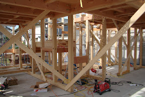
I learnt in first-year engineering classes that squares and rectangles are not a good idea for a structure, as they create a mechanism. The top can swing from side to side, turning from a rectangle into a parallelogram. If it keeps swinging, as it well might in a strong earthquake, the parallelogram turns into a horizontal straight line with the ceiling meeting the floor. To stop this, you need triangles. 

Our first-year engineering project, as I remember, was to design a structure--basically a bridge-- that would hold one tonne across a span of one metre. Most people built a square-based pyramid, with a hook at the top to hold the weight, and a beam diagonally across the square base to turn the square into two triangles and avoid the mechanism. My group made a tetrahedron: a triangular-based pyramid, so there were no squares to start with. This is the basis of the geodesic dome, which is a very light structure. Our "bridge" weighed a little over half the next heaviest design, fulfilling the goal of the engineer to build something that will do the job using the least necessary resources.

Anyone can build a bridge, we were told, but an engineer will build a bridge that is strong enough for its purpose, using as few resources as possible. 


I really don't know very much beyond first-year engineering, but I can't help feeling that there's just far too much wood in the structure of the house, and it's all in mechanisms. When we're talking about shelves and internal woodwork, I'm constantly being told that solid wood is really expensive, and we need to use laminated wood, or fibreboard. Then I see huge chunks like this being used where the roof meets the walls: 

The lateral strength is coming from kenaf board, imported from Malaysia and made from a baste fibre. A package was left on the balcony the other day, which alarmed me somewhat as it has a "No wet" sign and an umbrella. The architect assured me that this just meant the contents should not get wet, and it would be fine to leave the palate out in the rain.

The kenaf board is being put around the outside of the pillar and beam structure, then the batsu can all be removed. It doesn't look very rigid, but according to this paper it seems to be strong along its length. 

Tuesday, 14 June 2011

Tower of Babel


Just interesting to note four different writing systems used in four characters on each pillar. "1F" combines arabic numerals and roman letters to indicate the first floor. The house is divided into a grid where Chinese numbers indicate the position from north to south, and Japanese hiragana indicate the position east to west. For the carpenter, the zero point is the north-east corner. The architect, on the other hand, starts with X0 and Y0 in the bottom left hand corner of the drawing: the south-west corner.

The order of the hiragana is not the phonetic order usually used in teaching (a i u e o ka ki ku ke ko...あいうえおかきくけこ) but the older order, i-ro-ha order (i ro ha ni ho he to chi ri nu wo... いろはにほへとちりぬを). This order came from a poem written around a thousand years ago, that contained each syllable only once. Read more on wikipedia. they changed to the new order, based on Sanskrit, apparently, in the Meiji reforms in the latter 19th century. Iroha is still alive and well in house building.  

Friday, 3 June 2011

All in a day's work

Yesterday there was blue tarp, filled with puddles, and today it looks like a house.

When I got there a little after 8am, most of the pillars for the first floor were in place. When they knocked off a little before six, they had reached the roof. Tomorrow they should get the rafters and the bottom of the roof on, and it will be ready for the solar panels, which arrive on Tuesday.


It's impressive what seven men with tabi on their feet and tools belts around their waists can do with a crane and seven truckloads of wood. 

The wood was all ready cut and in many places it looked like a giant puzzle that had been set for the carpenters by the architect, who was standing watching from the edge of the site for a lot of the time.

It's amazing how quickly this has turned from a stagnant pool of concrete into something that really resembles the house that we've been planning for the past two years. It's a bit like a sumo bout where they spend half an hour position themselves and eyeing each other up, then the action is over in about three seconds.


Yesterday I was looking at puddles in tarpaulin, and today I was walking around upstairs. A link has finally been made between the building in my head and a solid and substantial house we can live in!

Saturday, 26 March 2011

Roof going round in circles

The foundation is racing ahead, but it's still not clear what is happening on the roof.  This needs to be decided so that the order can go to pre-cut the wood, and until that happens there will be no pillars, which will be needed to hold the roof up.

The South-facing roof is solar. Until recently solar roofs meant building a normal roof (compliant with the regulations for fireproofing and waterproofing) and then solar installers coming along and drilling holes in it to fit on their panels. Drilling holes is fair enough for retro-fits, but for new builds this seems foolish, especially if you're trying to get a highly insulated, airtight roof. Using a different construction does not meet their installation requirements and you lose their guarantee, and the panels themselves don't qualify as roofing. 

Last July one roof maker, Caname, who started out making roofs for temples, introduced a solar roof that meets the regulations for roofing, so there is no need for a double roof and, at least in terms of design, a more elegant solution is possible. Economically this should also make sense, but design simplicity does not always correlate with economics.

So, all we have to do it build up to the rafters, then Kaname will put their roof on top of it.  As long as they've got something they can put a waterproof sheet over, and into which they can screw the corrugated steel roofing which they mount the panels onto, everything will be fine.  The Kaname construction allows air flow under the panels, which is important to keep temperature down on the panels, which keeps efficiency up. Corrugated steel should work well for this, increasing the surface area and taking heat away by convection and conduction.

It's usually practice in Japanese building to have an air gap between the insulation layer and the external wall or roof.  As Kaname are putting corrugated steel on top, as well as providing air flow for the panels, this should also provide an air gap for the insulation. The reason for the air gap is in case humidity builds up and needs somewhere to go. Not everyone believes this is a good idea, and any gaps potentially can attract insects or even bats. The practice seems to have evolved to cover up for any problems with humidity, although, in theory at least, a well designed wall should not allow humidity to build up to turn to condensation. Also in theory, the gaps around the corrugated sheet should work both ways, but I've been battling both the roofer and the insulator (two different contracters) who seem keen to have things done their own way, and are looking at an assembly of parts rather than the whole, which was the main reason why Kaname seemed so appealing. 

However, there's also the west wall. In our wisdom http://minuszeroeco.blogspot.com/2010/04/west-wall.html, we decided that the house should not be square.  As the plot is not square, and non-square rooms do interesting things with space perception, this seems to be the correct decision long term, but when it comes to this issue, (and no doubt countless others that will emerge) it's causing problems. Kaname only make square roofs, so there is going to be a one metre overhand at the South west corner that needs to be supported somehow. 

One possibility is to get the rafters to stick out of the side of the house to support the overhand.  There are two problems here. In the original plan the rafters run up and down, north-south. Changing all of the rafters to run side to side, east-west seems to have been too difficult for the architect to adapt to without changing the whole structure. More seriously the rafters sticking out will lead to thermal losses and thermal bridge effects, sucking the heat out of the house. 

So we reached a plan to put the waterproof roofing sheet on top of the rafters (where the insulation layer ends) then put horizontal beams on top of that, which can stick out to the west and take the load of the overhanging corner. The panels need to be fitted with screws at horizontal intervals of 160mm and vertical intervals of 830 mm. Horizontal beams can cope with this, but if they are mounted horizontally, there are fears of beams twisting and the roof rolling off. The thinner the beams are, the less of a problem this is, but the beams need to all be the same thickness as the solar roof is flat, and they need to be thick enough to support the overhang. Extra beams can be added to the west to make this stronger. 

Another problem is that the solar roof installers need to add the roofing sheet, which would mean them making two trips, with some carpentry in between, rather than just coming and doing the whole job in one day. It's also not clear how they would feel about people making holes in the waterproof layer. 

The builder seemed much happier with vertical beams and some construction board mounted on top, although that will mean another air space and another layer of tyvec or some barrier sheet to stop any moisture that gets in there.  They pointed out that this would stop overheating in the summer, but we already have solar panels on the roof, and almost half a metre of insulation, so over-engineering is a much bigger concern to me than overheating!

So far all attempts to keep the design simple seem to be riddled with complications, and "simple" means very different things to different people!